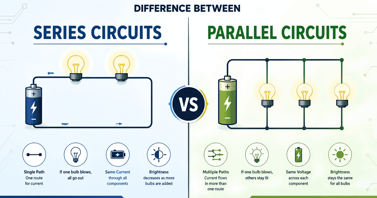
Switch off one light in your house and the others stay on. That is because your home is wired in parallel. But in an old-fashioned string of Christmas lights, if one bulb blows the whole string goes dark. That is because they are wired in series. The difference between series and parallel circuits affects how current flows, how voltage is shared, and what happens when one component fails. This guide explains both circuit types clearly with real examples so you can answer any GCSE Physics question on this topic with confidence.
In a series circuit, all components are connected in a single loop. The same current flows through every component and the voltage is shared between them. If one component breaks, the whole circuit stops working. In a parallel circuit, components are connected in separate branches. Each branch gets the full voltage and carries its own current. If one component breaks, the others continue to work.
Difference Between Series and Parallel Circuits: Comparison Table
| Feature | Series Circuit | Parallel Circuit |
|---|---|---|
| Connection | All components in one single loop | Components in separate branches |
| Current | Same current flows through all components | Current splits between branches |
| Voltage | Voltage is shared between components | Each branch gets the full supply voltage |
| Resistance | Total resistance increases with each component added | Total resistance decreases with each branch added |
| If one component fails | The whole circuit stops working | Other branches continue to work |
| Brightness of bulbs | Bulbs are dimmer as voltage is shared | Bulbs are brighter as each gets full voltage |
| Used in | Simple switches, some sensors, old Christmas lights | Home wiring, car electrics, most real circuits |
| Complexity | Simpler to build | More complex but more practical |
What is a Series Circuit?
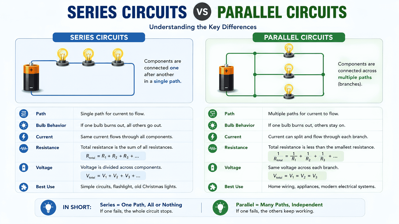
To understand the difference between series and parallel circuits, start with series circuits. In a series circuit, all the components are connected one after another in a single loop. There is only one path for the current to flow through. The current must pass through every component in the circuit before returning to the power source.
Key rules for series circuits:
- Current is the same at every point in the circuit. If you measure the current before the first bulb, between two bulbs, or after the last bulb, you get the same reading.
- Voltage is shared between the components. If a battery provides 12V and there are three identical bulbs, each bulb gets 4V.
- Resistance increases as more components are added. The total resistance is the sum of all individual resistances.
- If one component fails, the circuit is broken and no current can flow anywhere. All components stop working.
The formula for total resistance in a series circuit is:
Total resistance = R1 + R2 + R3
What is a Parallel Circuit?
A parallel circuit is the other half of the difference between series and parallel circuits. In a parallel circuit, components are connected in separate branches alongside each other. There are multiple paths for current to flow through. Current splits between the branches and each branch operates independently.
Key rules for parallel circuits:
- Voltage is the same across every branch. Each branch receives the full supply voltage from the battery or power source.
- Current splits between branches. The total current from the battery equals the sum of the currents in each branch.
- Resistance decreases as more branches are added. Adding more parallel branches gives current more paths to flow through, reducing overall resistance.
- If one component fails, only that branch is affected. All other branches continue to work normally.
The formula for total resistance in a parallel circuit is:
1/Total resistance = 1/R1 + 1/R2 + 1/R3
The Difference Between Series and Parallel Circuits in Current and Voltage
The most important part of the difference between series and parallel circuits for GCSE exams is understanding what happens to current and voltage in each type. This is tested in almost every electricity question.
In a series circuit:
- Current is the same everywhere: I = I1 = I2 = I3
- Voltage adds up to the supply: V = V1 + V2 + V3
In a parallel circuit:
- Voltage is the same across every branch: V = V1 = V2 = V3
- Current adds up to the total: I = I1 + I2 + I3
A useful way to remember this: in series, current is constant and voltage splits. In parallel, voltage is constant and current splits. The two circuit types are exact opposites in how they handle current and voltage.
Example 1 – Home lighting (Parallel circuit):
The lights and appliances in your home are all wired in parallel. Each light or appliance is on its own branch of the circuit, connected directly to the mains supply. This means every device receives the full 230V supply voltage. When you turn off one light, the others stay on because each branch operates independently. If all lights were wired in series, switching off any one of them would plunge the whole house into darkness.
Example 2 – Old Christmas lights (Series circuit):
Traditional Christmas tree lights were wired in series. All the bulbs were connected in one continuous loop. This is why when one bulb blew, the entire string went dark. Finding the faulty bulb meant testing each one individually until the string lit up again. Modern Christmas lights are wired in parallel so that one faulty bulb does not affect the rest of the string.
Example 3 – Car electrics (Parallel circuit):
A car’s electrical system is wired in parallel. The headlights, indicators, radio, windscreen wipers, and all other electrical components are on separate branches. If your car radio stops working, your headlights still function. If your indicators fail, your windscreen wipers still work. The parallel circuit design means individual component failures do not shut down the entire electrical system.
Example 4 – Simple torch (Series circuit):
A basic torch is a simple series circuit. The battery, switch, and bulb are all connected in one loop. When you press the switch, it completes the circuit and current flows from the battery through the bulb and back. If the bulb breaks or the battery runs out, the circuit is incomplete and the torch stops working. The series design is fine here because there is only one component that needs to work.
Example 5 – Battery connections (Series and parallel):
Batteries themselves can be connected in series or parallel. Connecting batteries in series increases the total voltage. Two 1.5V batteries in series give 3V. Connecting batteries in parallel keeps the voltage the same but increases how long they last, as the current demand is shared between them. This distinction is important in designing portable electronics and electric vehicles.
Series = Single path. Parallel = Plenty of paths.
Series circuit – think of a series of dominoes in a single line. If one falls over in the wrong direction, they all stop. One path, one failure stops everything. S for Single path, S for Series.
Parallel circuit – think of a set of parallel lanes on a motorway. If one lane is blocked, traffic moves through the other lanes. Plenty of paths means one failure does not stop the rest. P for Plenty of paths, P for Parallel.
For current and voltage: Series shares voltage. Parallel shares current. Write this on your hand before the exam.
Quick Quiz: Series or Parallel?
1. All components are connected in one single loop and share the same current. Is this a series or parallel circuit?
2. Each branch receives the full supply voltage and operates independently. Is this a series or parallel circuit?
3. One bulb in a string of lights blows and all the other bulbs go out. What type of circuit is this?
4. The lights in your home stay on when you turn off one light switch. What type of circuit is your home wired in?
5. In which circuit type is the voltage the same across every component?
Difference Between Series and Parallel Circuits in Exams
The difference between series and parallel circuits is tested in almost every GCSE Physics electricity paper. You need to be able to draw circuit diagrams using correct symbols, calculate current and voltage in both circuit types, explain what happens when a component is added or removed, and give real world examples of where each type is used. Always use the correct terms: current, voltage, resistance, and use the equations V=IR and the rules for series and parallel circuits to support your answers.
Common Mistakes to Avoid
Mixing up which quantity is the same in each circuit:
In a series circuit, current is the same everywhere and voltage is shared. In a parallel circuit, voltage is the same everywhere and current is shared. Students regularly reverse these two facts. Use the memory trick above and practise applying these rules to circuit diagrams before your exam.
Saying adding components to a parallel circuit increases resistance:
This is the opposite of what happens. Adding more branches to a parallel circuit gives current more paths to flow through, which reduces the total resistance. This is counterintuitive but important. Adding components to a series circuit does increase resistance, but adding branches to a parallel circuit reduces it.
Drawing circuit diagrams with incorrect symbols:
GCSE Physics requires you to use standard circuit symbols. A cell is drawn as a long and short line. A bulb is a circle with a cross inside. A resistor is a rectangle. A switch is an open gap in a line. Using incorrect or made-up symbols will lose you marks even if your understanding is correct. Practise drawing the standard symbols until they are automatic.
Frequently Asked Questions
What is the main difference between series and parallel circuits?
The main difference between series and parallel circuits is the path current takes. In a series circuit there is only one path for current to flow through all components. In a parallel circuit there are multiple paths, one for each branch. This single difference leads to all the other differences in how current, voltage, and resistance behave in each type of circuit.
Why is parallel wiring used in homes rather than series?
Homes are wired in parallel for two main reasons. First, each appliance and light receives the full supply voltage, which means they all work at their correct power levels. In a series circuit, the voltage would be shared and appliances would not work properly. Second, if one appliance or light fails in a parallel circuit, all the others continue to work. In a series circuit, one failure would cut power to the entire house.
What happens to the brightness of bulbs in series versus parallel?
Bulbs in a parallel circuit are brighter than bulbs in a series circuit connected to the same battery. In parallel, each bulb receives the full supply voltage so it operates at full brightness. In series, the voltage is shared between the bulbs so each one receives less voltage and glows more dimly. Adding more bulbs to a series circuit makes all the bulbs even dimmer because the voltage is shared further.
Can a circuit contain both series and parallel sections?
Yes. Many real circuits are combinations of both series and parallel sections. For example, a switch controlling a set of parallel lights is in series with the parallel section. When the switch is open, no current flows to any of the lights. When the switch is closed, current flows through all the parallel branches. These are called series-parallel circuits and they are common in real electrical systems.
For more on electric circuits, visit BBC Bitesize Physics: Electric Circuits.
Also read: Difference Between Speed and Velocity and Difference Between Mass and Weight to build your complete understanding of GCSE Physics.
Once you understand the difference between series and parallel circuits, electricity questions in your GCSE Physics exam become much more straightforward to answer with confidence.
